Help - Create project from Structure
Create project from structure
In this section, users can launch a new project starting from a structure in order to set it up for a Molecular Dynamics simulation.
Provide structure
Upload PDB File
Upload a PDB file structure from your computer with a maximum size of 50MB.
Once the file is selected, click the Submit button to proceed to the following step.
PDB ID
Upload a PDB file structure from its corresponding PDB ID. Start writing the PDB ID code and an autocomplete system will show you the different options available in the Protein Data Bank.
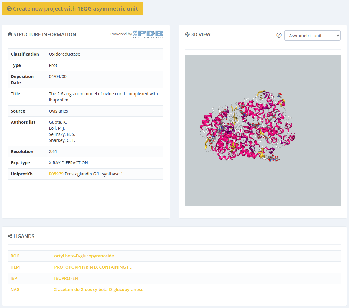
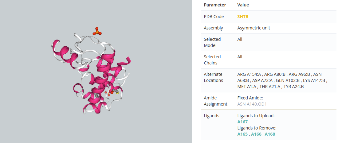
Once the structure is selected, it can be previewed in 3D. Different assemblies of the structure (if available) can be selected as well.
When all the data is selected, click the Submit button to proceed to the following step.
AlphaFold
Upload a PDB file structure generated through AlphaFold from its corresponding Uniprot ID. Start writing the Uniprot ID code and an autocomplete system will show you the different options available.
Once the structure is selected, it can be previewed in 3D.
When all the data is selected, click the Submit button to proceed to the following step.
Browse
Perform a search on the Protein Data Bank. Write a text in the input box and the system will search this text in the header and the compound of each Protein Data Bank structure.
Once the results are shown, users can select either by structure ID or by ligand ID:
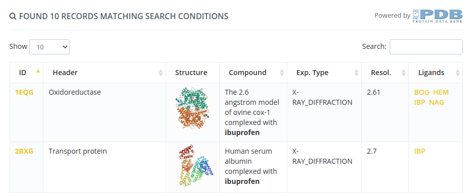
Selecting by structure ID will open a page with all the properties of this structure. Clicking in the Create new project button will proceed to the following step selecting this structure.
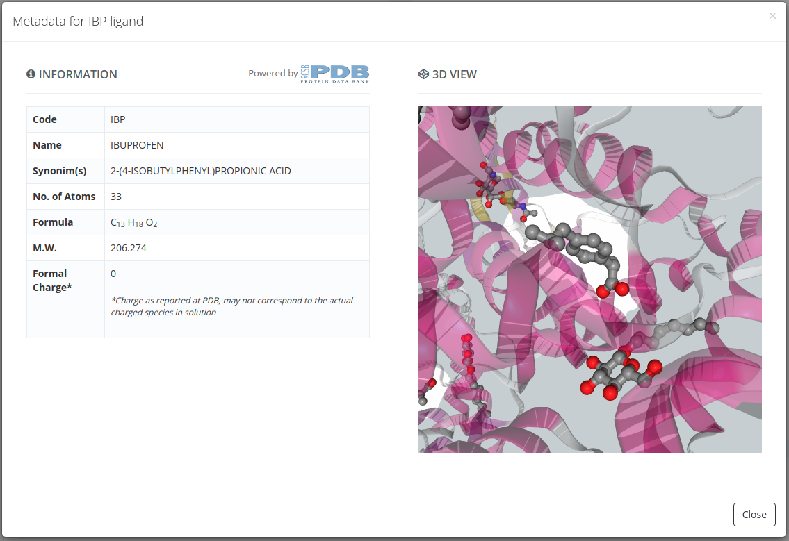
Selecting by ligand ID will open a page with all the properties of the parent structure of the selected ligand, but with a modal overlay with the ligand properties. Closing this modal and clicking in the Create new project button will proceed to the following step selecting this structure.
Check structure
In a Molecular Dynamics simulation, the correctness of input structures is crucial. Small errors in the input structure may cause MD simulations to become unstable or give unrealistic trajectories.
The purpose of the initial Structure checking page is to check for the most common problems in the input of MD simulations, allowing the user to select possible solutions when available. Besides, structure checking allows to select fragments of the system to be simulated in the case that alternate models or multiple subunits are present in the incoming structure.
An interactive 3D View provides additional help in assessing the significance of errors found. Please note that MD itself can correct some of the problems found (specially steric clashes), but others can only be corrected by editing the structure beforehand.
In summary, we can divide the Check structure section in four subsections:
3D View
In this subsection we can see all the time a 3D representation of the structure. This subsection has an interactive relationship with the rest of subsections, so for instance, when we select a ligand, it is highlighted in the 3D representation.
This 3D view has some controls for spinning, centering and taking a screenshot of the structure. Also a full screen button is available for making this workspace more comfortable for small screens.
There are structure controls, as well: change of background, change of representation style, change of color, change of ligand representation and enable / disable water and ions in the representation.

System configuration
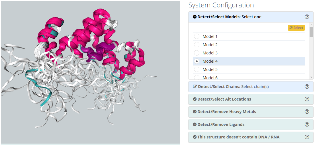
The system configuration subsection consists of a list of possible options to choose for the system to be simulated:
Detect/Select Models
For PDB files containing multiple models (common for instance in NMR obtained structures), only one of the models can be simulated. The interface shows you the list of possible structure models to choose. When chosen, all checking parameters are automatically recomputed with the selected model.
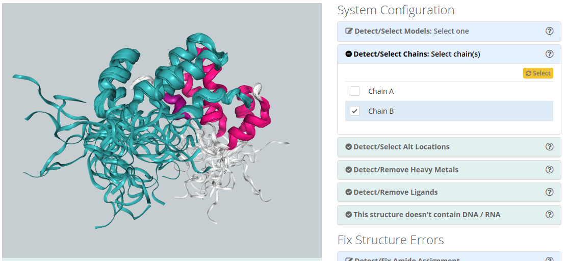
Detect/Select Chains
For structures containing several Chains, users can select the ones to be included in the simulation. A 3d widget helps in the identification of the chains, highlighting them when passing over the name with the mouse pointer. Be careful that selecting non complete structures may lead to unrealistic MD trajectories.
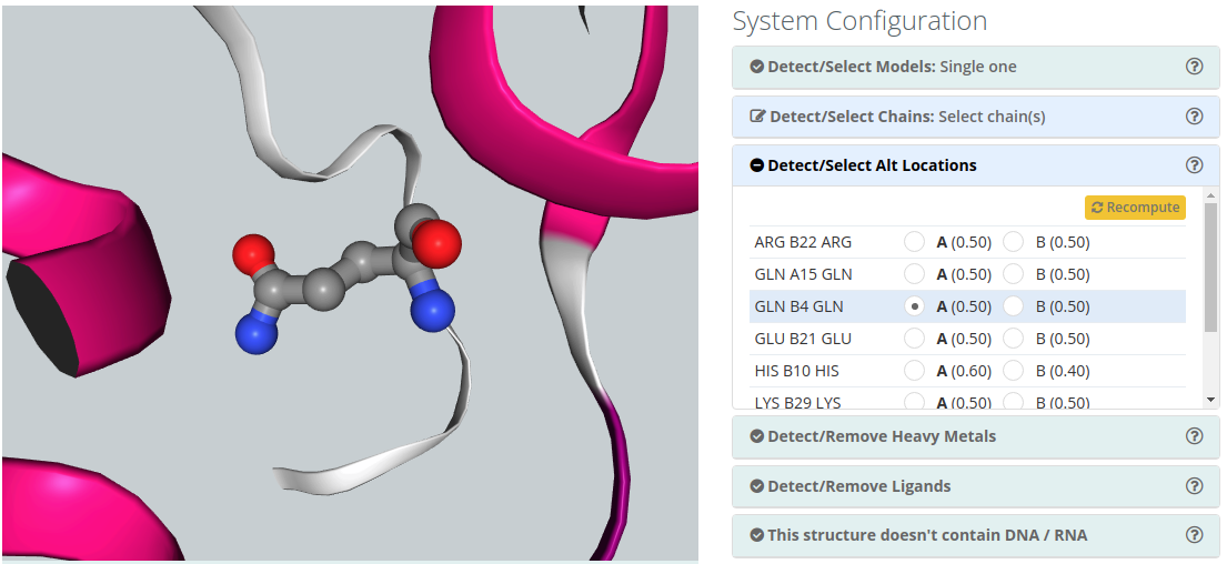
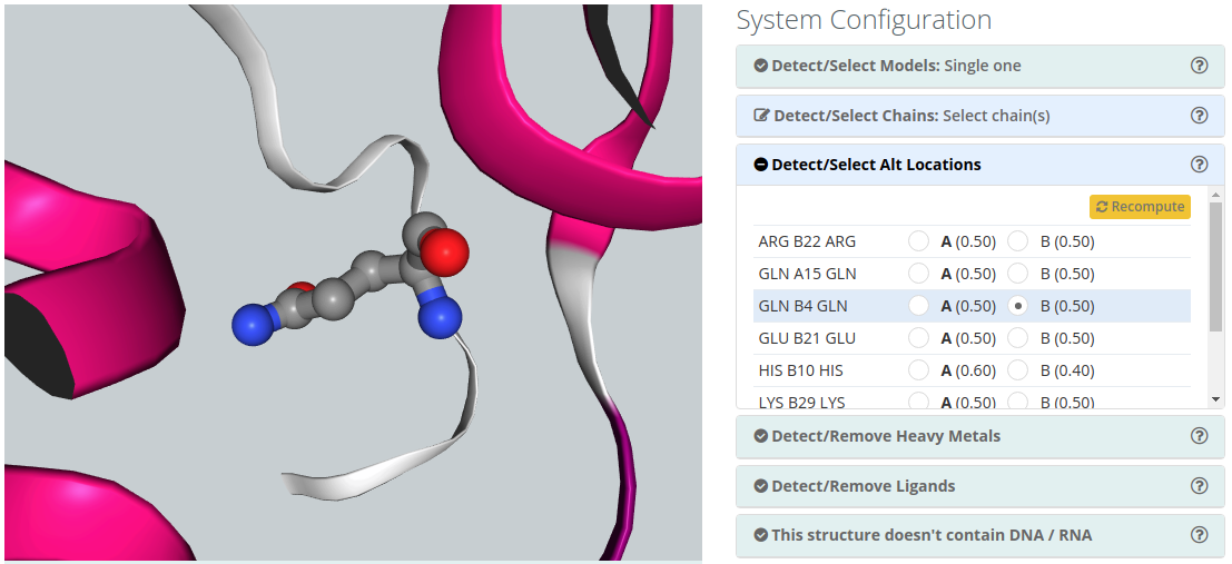
Detect/Select Alt locations
Alternate Location indicators are used for atoms where more than one position is detected. Within a residue, all atoms that are associated with each other in a given conformation are assigned the same alternate position indicator. Users can choose the residue alternate location of interest helped by a 3D view visualizer.
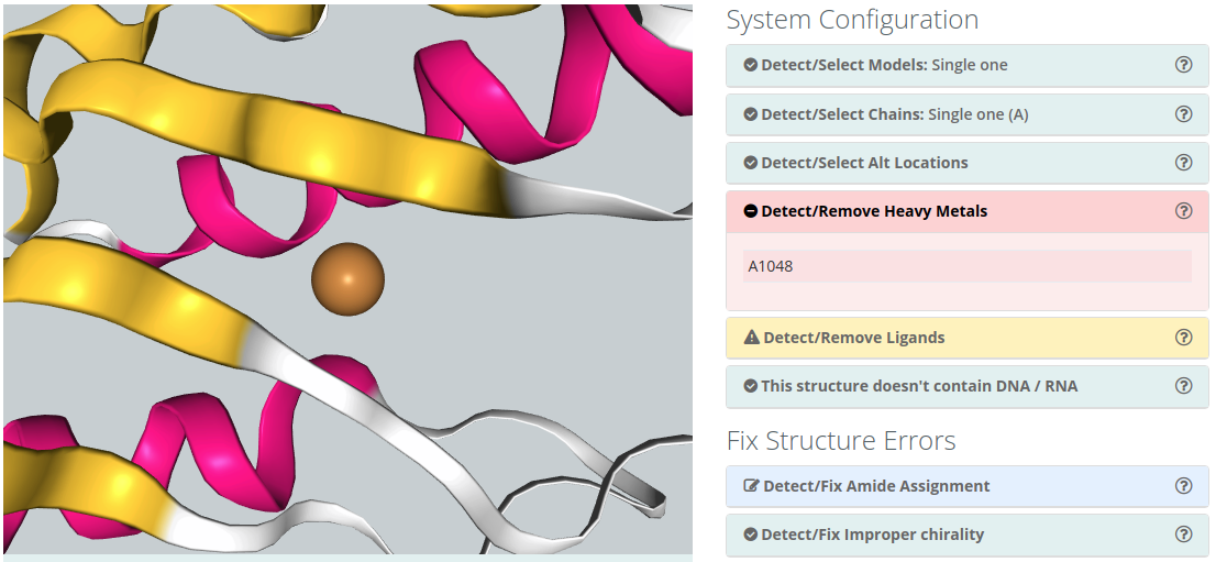
Detect/Remove Metals
Metals (Mg, Zn, Mn, Mo, Ni, Fe, Co, Cu, Hg, Cd, Ag, Au) are usually found making coordination complexes with protein residues. A typical example is the so-called Zinc finger, where a Zn ion is coordinated by cysteines and histidine residues, forming structural motifs that help stabilize the structure. Metal complexes involve a complex chemistry and are not normally covered by standard force-fields as they require a complete re-parametrization of both metal and ligands. Simulations of such complexes would normally require the setting of distance restrains to maintain the coordination structure.
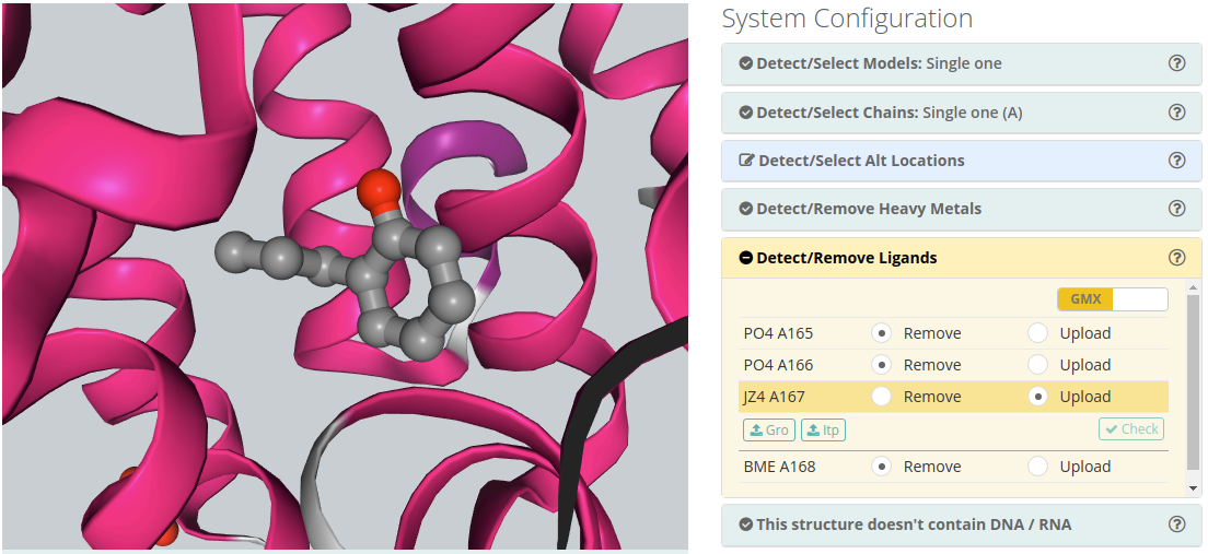
Detect/Remove Ligands
Ligands
The majority of the structures in the Protein Data Bank have non-standard residues included, identified as "heteroatoms" in the structure. Molecular dynamics force-fields contain parameters for standard amino acids and nucleotides but not normally for such compounds. To include a ligand in the simulation, the complete description of the ligand structure and the corresponding force-field parameters should be provided.
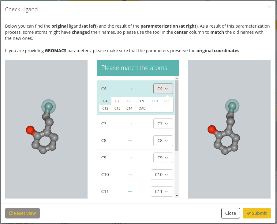
Both GROMACS (.gro and .itp files) and Amber (.lib and .frcmod files) parameters can be provided. Once both parameter files are provided, clicking the Check button will open a new modal window with the original ligand at left, a list of corresponding atoms in the center and the new ligand generated from the provided parameters. Users must be sure that the equivalence between atoms is correct, and amend it if necessary.
If you are providing GROMACS parameters, please make sure that the parameters preserve the original coordinates.
Please note that the default behaviour of BioBB Workflows checking phase is to remove ligands from the structure.
Ions
To include an ion in the simulation, you just need to click the Include option in the selectable menu.
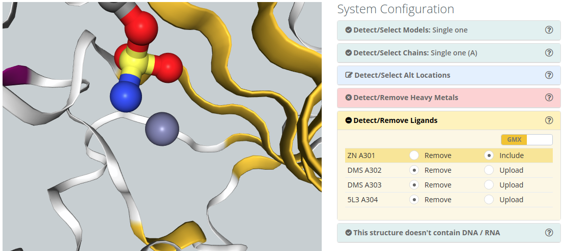
Please note that the default behaviour of BioBB Workflows checking phase is to remove ions from the structure.
Structure contain or doesn’t contain DNA / RNA
BioBB Workflows can work not only with proteins but also with nucleic acids and even with protein-DNA and protein-RNA complexes, however this feature has not been extensively tested. The structure checking process informs about the existence of nucleic acids in the input structure. Removal of nucleic acids if desired can be done in the chain selector.
Fix Structure Errors
The structure errors subsection consists in a list of possible structure errors that can be fixed by users:
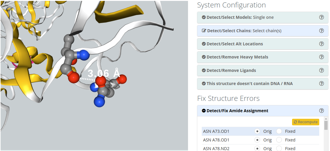
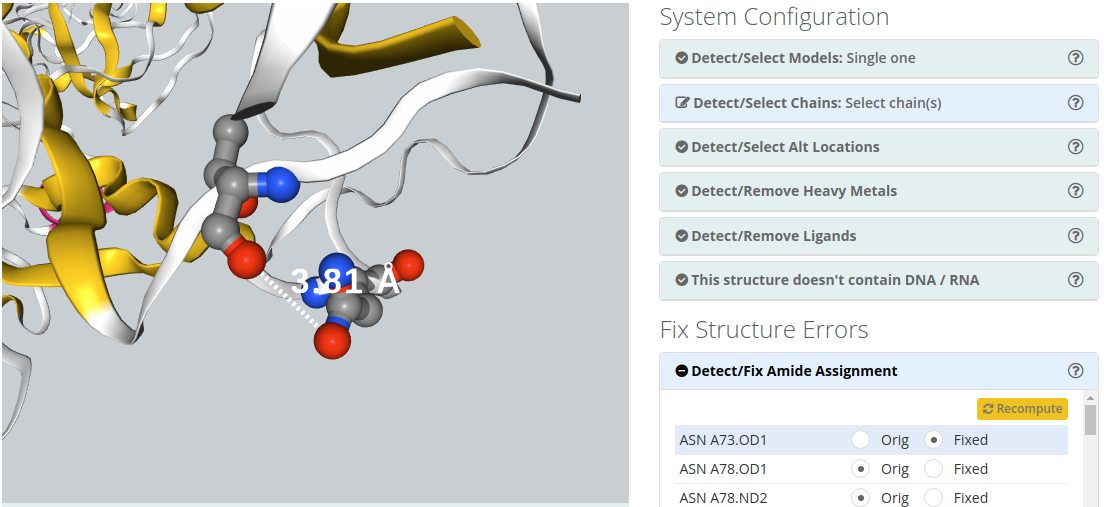
Detect/Fix Amide Assignment
Amide Groups in the side chains of Glutamine and Asparagine (Gln, Asn) residues can act simultaneously as hydrogen bond donors and acceptors. The electron density near the nitrogen and oxygen atoms of these functional groups is compatible with two rotamers related by a 2-fold symmetry axis. Therefore, electron density maps obtained from X-ray diffraction experiments can be wrongly interpreted leading to improper amide assignments. Users can choose the best fitted amide group configuration helped by 3D view.
Structure Warnings
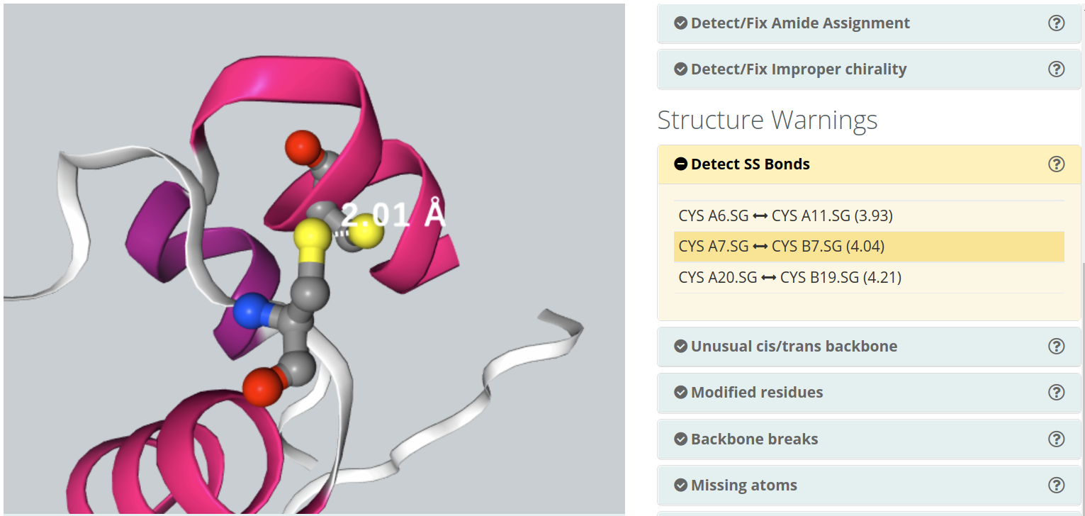
The structure warnings subsection consists in a list of possible structure errors / warnings in the structure:Detect SS Bonds
Disulphide bonds are covalent bonds usually formed by a pair of thiol groups. They are also called SS-bonds or disulphide bridges. As they are covalent bonds, it is of great importance in a simulation to take them into account. In fact, SS-bonds are known to have an important structural role in protein structure and stability. Setup procedures can detect and link thiol groups forming disulphide bridges, but it is important to know whether the structure contains such covalent bonds. 3D widget will show the structure's disulphide bonds, as well as the distance between the sulphur atoms involved.
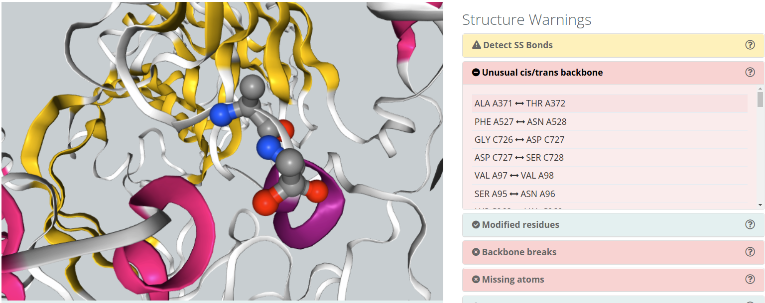
Unusual cis/trans backbone
Cis/trans isomerism describes the orientation of functional groups within a molecule where a bond has a limited possibility of rotation. Peptide bonds have a considerably double bond character and present cis/trans isomerism. Nearly all peptide bonds appear in the trans, whereas cis configuration is sometimes found in Proline residues. Omega torsion angle (ω) is computed to identify unusual cis/trans configurations in peptide bonds.
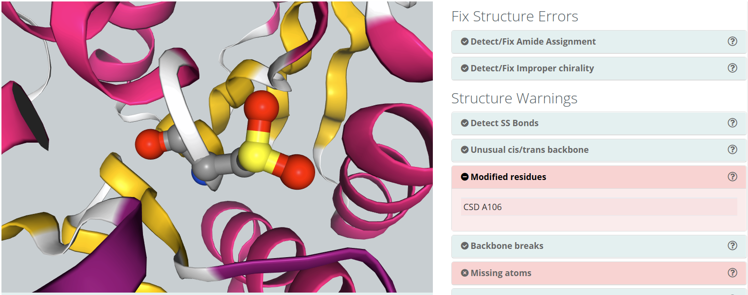
Modified residues
Some of the structures in the Protein Data Bank have modified residues included. These residues, generated by, for example, post-translational modifications (e.g. acetylation, ubiquitination, methylation, hydroxylation), are identified as "heteroatoms" in the structure. Molecular dynamics force-fields contain parameters for standard amino acids and nucleotides but not normally for such compounds. To include a modified residue in the simulation, the complete description of the residue structure and the corresponding force-field parameters should be provided in the Detect/Remove Ligands section.
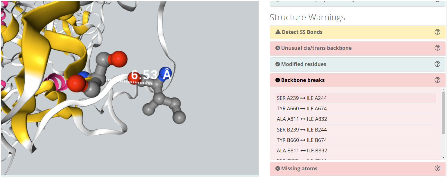
Backbone breaks
Flexible protein regions can have too low electron density to be detected in X-Ray diffraction experiments, and can be missing from PDB structures. This situation gives unrealistic structures where protein is split in several unconnected chains with new N- and C- terminal residues and buried protein regions become exposed to solvent. Simulation of such structures will give untrusty results and should be corrected by filling the missing gaps. BioBB Workflows detects gaps both from the residue numbering and the existence or non-realistic bond distances.
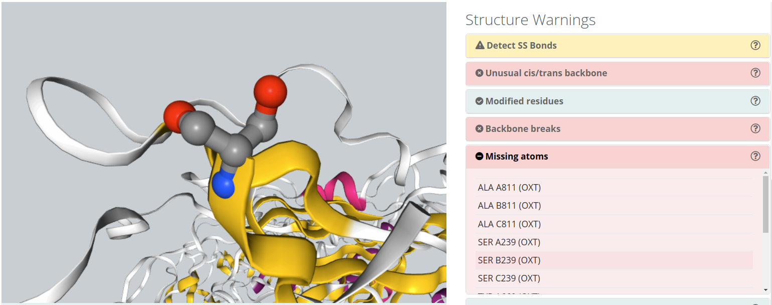
Missing Backbone Atoms
Flexible atoms from an amino acid (e.g. side chain atoms) can also have too low electron density to be detected in X-Ray diffraction experiments, and can be missing from PDB structures, similarly to what happens for certain protein regions. MD programs work with amino acid libraries that need all atoms to be present. Some MD packages tools are able to model these missing atoms, being easier to modeling side chain atoms than backbone atoms. BioBB Workflows detects missing atoms and shows them in the NGL visualizer. Depending on the type of missing atoms and the workflow chosen, this issue can led to errors in the topology generation.
Atom Clashes
Atoms that are too close in space can have a problem of energetic repulsion. BioBB Workflows provides the list of atom pairs and the corresponding distances that can have potential problems. Most clashes come from over-compactation of crystal structures and are naturally corrected on system setup or MD equilibration, but may lead to a significant distortion of the structure. Clashes are classified in different groups, depending on the atom types involved:
| Group | Description | Distance cut-off |
|---|---|---|
| Steric Clashes | Any atom pair | 1Å |
| CA Steric Clashes | Alpha-carbon atom pairs | 3.8 ± 1Å |
| Polar Donor/Acceptor Clashes 1 | Polar hydrogen bond donor/acceptor atom pairs | 1Å |
| Apolar Clashes 2 | Apolar atoms | 2.9Å |
| Ionic Positive/Negative Clashes | Positively/negatively charged atoms | 3.5Å |
1 Note that common polar clashes come from mis-assignment of side chain atoms in Asn, Gln, or Thr residues.
2 Note that possible apolar clashes can come from atoms neighbouring legitimate hydrogen bonds.

Summary checking
After the Checking Structure section there is a summary page with all the actions performed during the checking process.
Settings
In this section, users must provide a project name and, optionally, an email address for being notified once the workflow is finished. Take into account that some of the workflows can last several hours.
There are custom parameters for each workflow: when changing workflow, the custom workflow parameters change as well.
Workflows available if project has been created from structure:
GROMACS Set Up
Only available if the initial structure has no ligands or they have been removed during the Checking Structure process.
It has as an available option to prepare configuration files to run a long MD simulation in your own premises. Broadly explained in the HPC Section.
Click here for more information about this workflow.
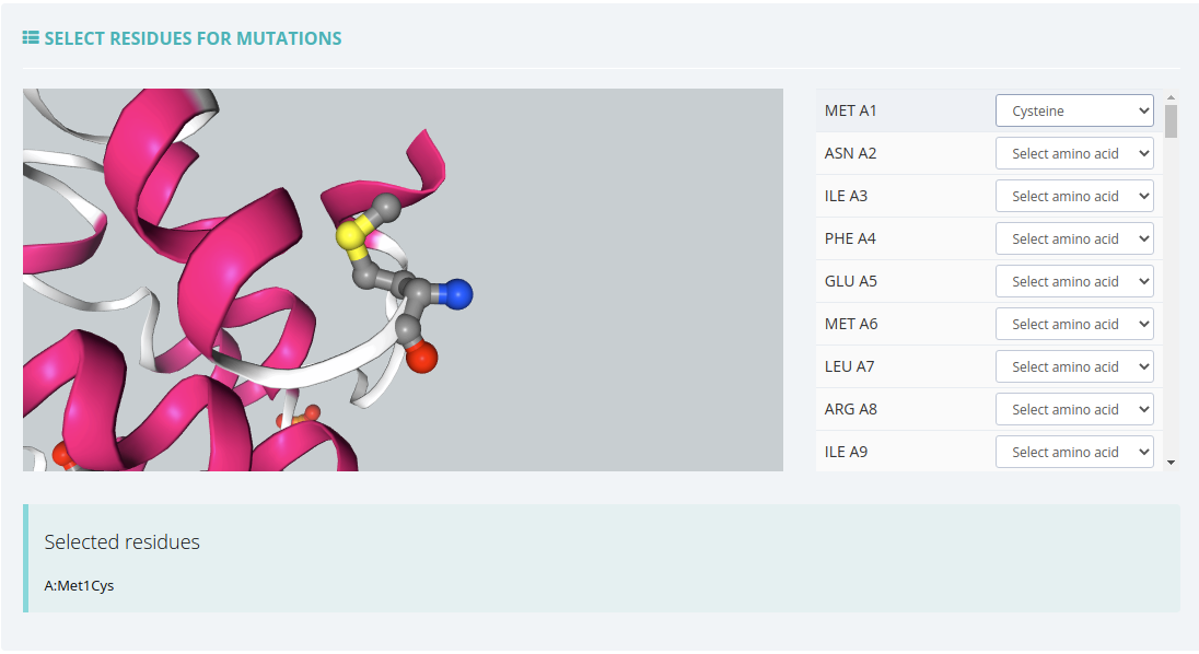
GROMACS Set Up with Mutations
Only available if the initial structure has no ligands or they have been removed during the Checking Structure process.
In this workflow, apart from the GROMACS Set Up parameters, there is a block for selecting the residues to mutate.
Click here for more information about this workflow.
Amber Set Up
Only available if the initial structure has no ligands or they have been removed during the Checking Structure process.
It has as an available option to prepare configuration files to run a long MD simulation in your own premises. Broadly explained in the HPC Section.
Click here for more information about this workflow.
GROMACS Complex Set Up
Only available if during the Checking Structure process, users have provided GROMACS parameters for a SINGLE ligand.
It has as an available option to prepare configuration files to run a long MD simulation in your own premises. Broadly explained in the HPC Section.
Click here for more information about this workflow.
Amber Complex Set Up
Only available if during the Checking Structure process, users have provided Amber parameters for one or more ligands.
It has as an available option to prepare configuration files to run a long MD simulation in your own premises. Broadly explained in the HPC Section.
Click here for more information about this workflow.
Run project
Before running the project, we can find a summary page with all the checking actions and workflow parameters, as well as a log of all the actions performed until this moment.
In this page, in the Download scripts section, users can download Python and YAML files for the sake of running the workflow at home. There are also available the CWL files for executing the workflow through Common Workflow Language. All the files have been customized with the parameters provided by users in previous steps.
Once all data is ok, we can click the Launch project button and the workflow starts showing its progress.
After finishing the running process, users will be automatically redirected to the output summary, broadly explained in the Outputs section.